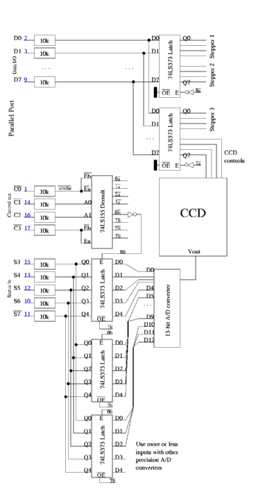
For now, I only build the stepper motor part, i.e. the two latches at the D0--D7 inputs and the multiplexer. For each stepper, four signal lines emerge from this circuit; they are amplified later on with this circuit (input lines are marked with IN; you need two of these per stepper):
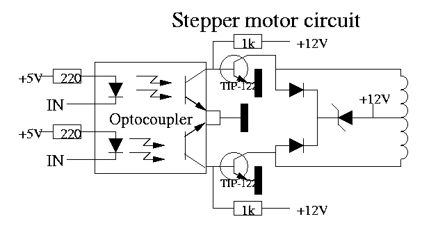

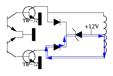
What about those two diodes and that zener diode? Windings (coils) have the nasty habit of counteracting changes in current through them. So, if you suddenly start sending current through a coil (current rises abruptly), the coil will work against you for a short time. Inversely, when you cut off the current (current drops), the coil will generate a current to counteract the current drop. Of course, the coil cannot keep generating this current for a long time (otherwise we'd have found a very simple solution for the energy crisis :-) ), but the current generated by the coil can be very strong during a brief period of time, and even destroy the transistors.
Monday march 20th 2000: I pay a visit to Gentronics with this shopping list:
| Quantity | Price (fr) | Description |
| 20 | 40 | 10k resistor |
| 5 | 125 | 74LS373 latch |
| 1 | 25 | 74LS155 demultiplexer |
| 1 | 15 | 74LS04 hex inverter |
| 1 | 75 | CNY74-4 optocoupler |
| 1 | 189 | Pre-made print ECS3 (bakelite, one-sided, islands per 3) |
| Total | 469 |
Tuesday March 21st 2000: at Radio Home I buy these things:
| Qty | Price(fr) | Description |
| 4 | 20 | 1N4007 diode 1A |
| 2 | 50 | Zener diode 30V 5W |
| 1 | 20 | 7805 5V voltage regulator |
| 8 | 80 | 0,1 microfarad condensator tantalum |
| Total | 170 |
Thursday March 23rd: at Gentronics I get some sockets for the chips I've bought:
| Qty | Price (fr) | Description |
| 5 | LC20 IC socket 20pin | |
| 2 | LC16 | |
| 1 | LC14 |
Friday March 24th: I take look at
Colin Electronics (in Lovendegem, which is an hour away by bike of where I live).
Unfortunately, they don't have any of MAX6160, MAX151, TC211, TC215 of KAF0401 in stock
(and also here, they've never heard about Kodak chips). Their advice is to
go and look at ... Radio Home. Yes indeed.
At TI's webpage, you can find a shockingly
tree Belgian
suppliers, so maybe ...: EBV,
SEI en Spoerle.
Only the last one has something on its homepage about CCD's
(do a Detailed Search, and search for CCD in Part Description).
Kodak and Maxim are noble unknowns for all three suppliers.
At Maxim's page,
one single
Belgian supplier can be found: Master Chips.
Saturday March 25th: again some stuff from Gentronics:
| Qty | Price (fr) | Description |
| 4 | 12 | 220ohm resistor |
| 4 | 120 | TIP-122 transistor |
| 1 | 25 | Bar-M-R-E pin-header |
| Total | 157 |
Monday evening April 3rd april:
Zeus WPI (Workgroup Informatics
of the university) gave me an old 386 to play with. Soon I discover that it
has no harddisk. So I enbark on a quest for a Linux version that fits on a floppy.
An eavening of net-searching reveals tomsrtbt,
which creates a special 1,7MB floppy (the standard way of using floppy's gives
you only 1,44MB) and pushes on it a more or less usably Linux. First I tried
Linux On A Floppy,
but I didn't manage to covince it to read floppy's.
Then I quickly wrote a simple test program and it's
midnight again ...
The program is inspired on the
Linux I/O port programming mini-HOWTO.
One thing to take care of is that in the makefile, I use the option-static.
The test program is compiled on a 'regular' computer, and there, much used functions
are not pasted into each program literally, but only a short reference to a centray
library of functions is stored. The mini-on-a-single-floppy Linux has no
(or at least not enough) of those libraries; therefore the functions have to be pasted
in the program, which of course can be done using -static.
You already guessed that by now, didn't you? :-)
Tuesday evening April 4rd: cleaned up the test program a little, but unfortunately enough nothing appears to come out of the parallel port!
Wednesday evening April 5th: some more modifications to the test program. More interesting, I discover why the parallel port didn't seem to do much: I forgot to solder some crucial wires on the print! It are the four wires that should send the D0/D1/D2/D3 signals that have passed the 10k resistors to the latch-chip. Therefore, the whole circuit gets no signals, including the places where I was measuring last night ... When I measure on the resistors itself, I see that the signals the test program sends out, effectively arrive.
Thursday evening April 6th: Finally I get signals out of the computer, now something else turns up of course :-) The 10k resistors seem to be a little too much. A logic 0 gives 0V before the resistors and 0.78V after them. The chips only recognize a logic 0 when the voltage is below about 0.5V. The logic 1 poses no problems: 3.56V before the resistor becomes 3.53V after (and 2V is already enough for a logic 1).
Friday April 8th: I fetch ten 1kOhm resistors at Gentronics, costing me 20fr.
Monday April 10th april: the print with the 1k resistors instead of 10k gives good result: a 0 comes through as 0.2V and a 1 as 3.55V. Unfortunately, the circuitry past the optocoupler still doesn't work. It appears I need to add a 1k resistor in the schematic of the stepper motor control.
Wednesday evening 12th april: added the resistors, and it works! Up to now, I've built half a stepper drive (which drives two of the four windings).
Thursday April 13th: I start building the other half of the stepper drive. I run out of 1k resistors, so I fetch another ten at Gentronics (20fr).
Friday april 14th: the other half is ready and running! I quickly write step.c that rotates the motor a number of steps to the left or to the right. Halfstepping also works.
Sunday October 29th: I send a fax to EBV Elektronik, SEI and Spoerle to ask some info about CCD chips.
Monday October 30th: I've already got a reply from Spoerle, alas it only says that they have nothing to offer for us. Which is a little strange since they have some TI CCDs on their homepage. Maybe the term ``CCDs for astrophotography purposes'' has been a little bit of a bad wording ...